
- SITEMAP
- CONTACT US
- 8618267732328
News
Credibility ,the lifeblood of enterprise!
- Fittings
- Butt Welding Fittings
- Forged Fittings
- 180 Degree Elbows
- 90 Degree Elbows
- 60 Degree Elbows
- 45 Degree Elbows
- 30 Degree Elbows
- Equal Tee
- Reducing Tee
- Concentric Reducer
- Eccentric Reducer
- Lap Joint Stub End
- Outlets
- Cap
- Bend
- Cross
- Coupling
- Stainless Steel Lateral Tee
- Bellows Expansion Joints
- Flexible Metal Hose
- Non-Standard/Custom Fittings
- Bleed & Flushing Rings
- Types of Flanges
- Anchor Flanges
- Blind Flanges
- Expander Flanges
- High Hub Flanges
- Lap Joint Flanges
- Long Weld Neck Flanges
- Nipoflanges
- Orifice Flanges
- Plate Flanges
- Ring Type Joint Flanges
- Reducing Flanges
- Slip On Flanges
- Socket Weld Flanges
- Spectacle Blind Flanges
- Square Flanges
- Spades & Ring Spacers
- Threaded Flanges
- Welding Neck Flanges


How should the thickness of the small end of an equipment flange be valued?
When calculating equipment flanges, should
the thickness of the small end be entered into the thickness of the small end
of the flange or should the thickness of the cylinder be entered?
This issue has been debated for a long
time. It is hard to convince each other that both flange thickness and cylinder
thickness should be entered because NB and GB150 are different.

The author suggests that the thinner part
(the thickness of the cylinder) should generally be entered into the software
for the following reasons:
1. Flange calculation countries
are using the Waters method
From the principle of calculation, the
flange is divided into 3 parts: ring plate, cone neck, and cylinder (straight
edge section). The three constitute two pairs of discontinuous connection
problems. Which cone neck height for h, cylinder height for h0 = sqrt (Bg0).
Generally, the straight edge height does not reach h0, and if the thickness of
the small end of the flange is entered, then it is on the adventurous side,
which corresponds to a long section of missing material. In terms of
computational modeling, the thinner part (thickness of the cylinder) should be
entered.
-C62/249")
For example, in the CODAP specification,
which also uses the waters method, the g0 and l0 = sqrt (Dg0) of the overall
flange is detailed. From the illustration, it can be visualized that the
thickness of the cylinder should be taken.
So many friends believe that persuasiveness is not enough.
In fact, in the mandatory Appendix 2 of ASME VIII I-2019, for the thickness of the small end, in the case shown in the above figure, the thickness of the thinner part, i.e. tn, should be taken.
2. Although GB150 for the thickness of the small end is written: "flange neck small end of the effective thickness", we can see how other specifications are described.
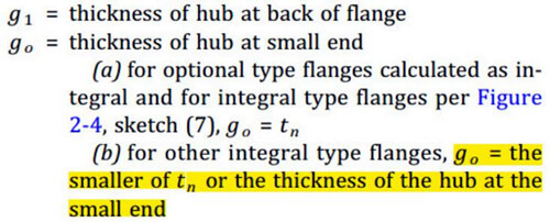
ASME for
the thickness of the big end is: "g1 = thickness of hub at back of flange.
"The small end thickness is:" g0 = thickness of hub at the small end.
"Small end thickness and did not mention the thickness of the small end of
the flange. EN13445 and ASME's English description is consistent. So, from the
description of the specification, the small end should be taken as the
thickness of the thinner part rather than the thickness of the small end of the
flange.
3. Flange stiffness is inversely proportional to g0 squared. The flange does not have a substantial increase in stiffness throughout the flange system just because the thickness of the small end has increased (the thickness of the barrel has not).
If the thickness of
the flange and the cylinder butt is very thin, the flange should be how the
deflection is still how to deflect, not because of the small end of the
increase of a little bit of material and make the whole stiffness has increased
by leaps and bounds. So, from the point of view of controlling the stiffness of
the flange should be entered into the thickness of the thinner parts.
4. From another aspect, for ASME/EN design,
there is no NB flange standard; their equipment flanges are made into a flange
neck length and cylinder thickness, which is not from the side of the input
should be thinner parts of the thickness.
But define h0 as a length that must be
guaranteed, then it is hard to explain why the overall flange and head can be
welded directly without the need to ensure that there is a length of h0. The
following figure is taken from standard GB150.3-2011 Figure 5-26 Convex head with flange.

Of course, it can also be understood from
the other side that the head has a reinforcing effect on the flange, the corner
of the head is subjected to compressive stress, the film stress at the small
end of the flange is tensile stress, and the effect of superposition with the
flange is to make the two stresses better. Therefore, the national norms of
such structures are considered that they can be separated and calculated
separately.
GB150 flange calculation does not take into
account the small end of the flange part of the ring film stress, such as ASME
flange calculation, which needs to calculate the thickness of the small end of
the flange in accordance with the internal pressure. GB150 does not take into
account may result in the thickness of the straight edge section is very thin,
and even the thin film stress cannot pass the case, the flange calculation
through. This can also cause some risks.

But is it true that the thickness of the
small end of the flange must be made the same thickness as the barrel? The
answer is not necessarily. The reason for this is that the Waters method is
interpreted from another angle.
Water's method requires that the cylinder and flange have the same load carrying capacity. However, the values of G0 and
h0 only take into account the geometry, but in fact their strength is
controlled by the permissible stress value and the geometry together. Geometry
alone (equivalent to only accounting for the bending stiffness of the flange) needs
to be more comprehensive, especially if the flange of the permissible stress is
lower than the permissible stress of the cylinder. Ensure that the flange
stress * flange thickness of the small end should not be less than the cylinder
stress * cylinder thickness.
For example, the flange (stainless steel)
permitted a stress of 80MPa, and the cylinder (carbon steel) permitted a stress
of 160MPa. The cylinder is taken 10mm, then the flange calculation to take the
thickness of the cylinder, the calculation will take much work to pass. Because
the small end of the flange takes 10mm, it may not be able to pass the local
film stress. At this time, we should also consider the geometry and strength.
The small end of the flange should be taken 10 * 160/80 = 20mm. In order to do Waters's
method of modeling assumptions, their strength is continuous. The small end of
the flange and the cylinder connection is as long as 1:3 trimming, and then the
butt can be.
This is described in ASME B16.5.
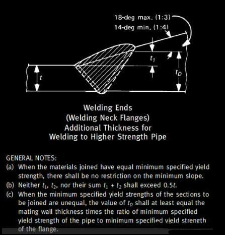
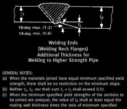
(c) is more detailed: when the minimum
yield strength of the two is not the same, the thickness of the small end of
the flange should be at least the thickness of the tube t multiplied by the
ratio of the stresses in the tube and the flange.
In summary, in general, the equipment flange calculation of the thickness of the small end should take the thickness of the cylinder, while the flange thickness of the small end should also be considered. The impact of the internal pressure film stress cannot be too small. When the flange and the permissible stress of the cylinder when the difference is more (it generally appears that the flange is stainless steel, but the cylinder is carbon steel composite plate), the flange thickness of the small end should reach the equivalent strength of the cylinder.

Tel No:+86-18267732328 / Email:[email protected]
Address:Longwan District, Wenzhou, Zhejiang Province, China.
Copyright Notice © www.yaang.com Yaang Pipe Industry Co., Limited All rights reserved.
Yaang Pipe Industry Co., Ltd. is an international supplier of piping solutions for flange, butt welding fittings, socket welding fittings and threaded fittings. Our products are widely used in different industrial fields, including oil and gas, chemical industry, petrochemical industry, power plant, pulp and paper industry, environmental and water conservancy engineering, engineering projects, etc.
